

HOW IS IT MADE


FINDING A GOOD REFERENCE
STEP 1
Finding the right reference ensures the design process achieves the best possible results.
We have an extensive library of blueprints and 3D models to achieve the most accurate proportions and dimensions.

FIRST SKETCH
STEP 2
The first sketch allows you to get an idea of how the model would look, integrating all the requirements at design and textures, it is a visual approximation to the paper model structure and its proportions.
From some visual references, the sketch is made where the client understands what details will be part of the 3D model and what parts will be created by means of textures.
ALIGNMENT
STEP 3
If we use more than one reference, we must ensure that they are aligned as precisely as possible in position, rotation, and scale.
If photographs are used, it is necessary to align each image with the angle and depth of the virtual camera.

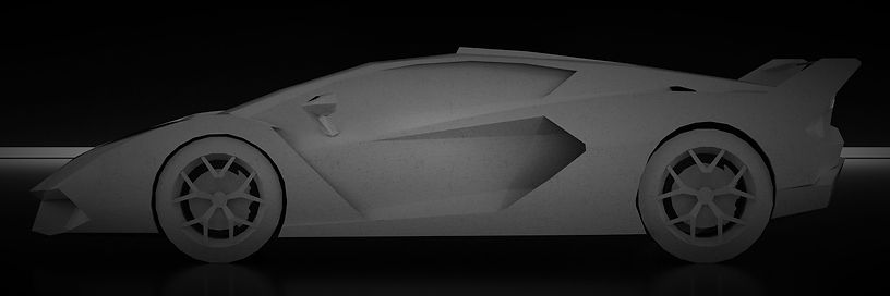
MODELING
STEP 4
Once the correct vectors of the model are obtained, the next step is to mount them in a modeling software that allows them to be kept at the same scale, the corresponding views are arranged and their positions adjusted so that, starting from the first vertex, we generate each vector according to the lines main of the model. At this point, the general geometry is more important than details such as the bulbs, it is necessary to have a good understanding of the real model and see which details are an essential part of the geometry of the car, and which parts can be highlighted by means of textures. Comparing the views, each vector is directed to generate the main form that builds the complete model and transform it into a solid object. It must be taken into account that a model for papercraft must reduce the details of the object to those strictly necessary, so its polygon is going to be very small if we compare it with normal 3D models.
TESTING UNFOLD
STEP 5
To review the first result of the 3D model, the model is transferred to another program to perform the unfold, determining where the cuts will go and the position of each part on sheets of paper to be printed. These pieces are determined from the first step of creating papercraft models, so the model we find in this step must match the first sketch.

FIRST BUILD
STEP 6
With the first assembly, flaws in the design process can be found, some errors in the model or better ways to give a better result, they are evaluated if details are missing or if there are details that are left over. This step is essential to be able to improve the model, thinking that it should be easily assembled for the public while maintaining good quality. This step is carried out with more than one user, allowing the possible shortcomings or improvements of the model to be more easily identified.
FIXING 3D MODEL
STEP 7
Knowing the improvements, the next step is to apply the necessary changes to the model to have a corrected and finished structure ready for assembly, thus reducing the chances of encountering difficulties for those who acquire the model and want to assemble it. With the final structure it is time to complement the details of the model that were not made physically, it is time to create textures.

CREATE THE TEXTURES
STEP 8
Starting from the orthogonal views of the model, the textures are distributed in the files that integrate all the details, several details can be integrated separately or it can be made in a single texture file . Contrary to the normal process of UV's where the division is made by pieces and these are overwritten in another program, to make the textures, orthogonal views of the model must be placed in a vector drawing program, working with separate defined layers were i can distribute details such as the main color, the dark parts, the mirrors, glass and bulbs, the lights and shadows of the model, and other details that can be grouped in layers. In the process of textures you cannot be austere, you must integrate the greatest amount of details that are relevant to give the model a better look and an impressive final result.
APPLYING TEXTURES
STEP 9
As the textures are not designed from UV's maps, it is necessary to manually accommodate the surfaces according to the generated texture files, the faces of the model to which a texture file corresponds are selected and placed in the model, from the largest details to the smallest.
RENDER TEST
STEP 10
With the textures applied, visual tests are carried out with different programs for preview and rendering, looking at the compatibility of the textures with the model and being able to thoroughly check the correct coupling of the textures in the model, verifying that it should look as originally planned.
FINAL UNFOLD
STEP 11
With the model finished and corrected, it is time to make the unfold of final pieces, the cuts that separate the model into different pieces, the size of the printing paper, the distribution of the pieces on the paper are declared and each is assigned piece an indicative, the number of pieces is determined, the final size and the files for printing are generated.
INSTRUCTIONS
STEP 12
Having clear the structure of the model with the parts and their names, an optimal assembly order is proposed for the model that allows its understanding at the time of assembly, step by step, piece by piece, a graphic explanation of the proper order of assembly of the model is given. model, is divided into chapters so that the user can easily understand how to go from the pieces to a finished model ready for exhibition.
FINAL BUILD
STEP 13
The assembly process in the instructions is applied and followed step by step to shape a high quality sample of the final model, a thick, shiny and resistant paper is chosen for the larger models, varying between opaline and propalcote with laser printing.

PROFESSIONAL PHOTO SHOOT
STEP 14
Once the model is finished, a photo session is carried out in order to share the result of a long design process and high quality modeling and texturing.
